FAQ
Please let us know, if you need any more information
A magnetic head is a device that can be used for two main purposes:
a) storing of an electrical signal on a magnetic medium
b) reading back magnetic data by converting it into an electrical signal.
Every magnetic head will fulfill at least one of both functions, although both functions can be combined into one head in several ways. All possible combinations will not be discussed here as the number of possibilities is huge. To make things not to complicated, both functions will be explained separately.
1) Writing process
For explaining how a write head works, a magnetic head is compared with an electromagnet. An experiment that nicely illustrates the functioning of an electromagnet is depicted in the illustration below.
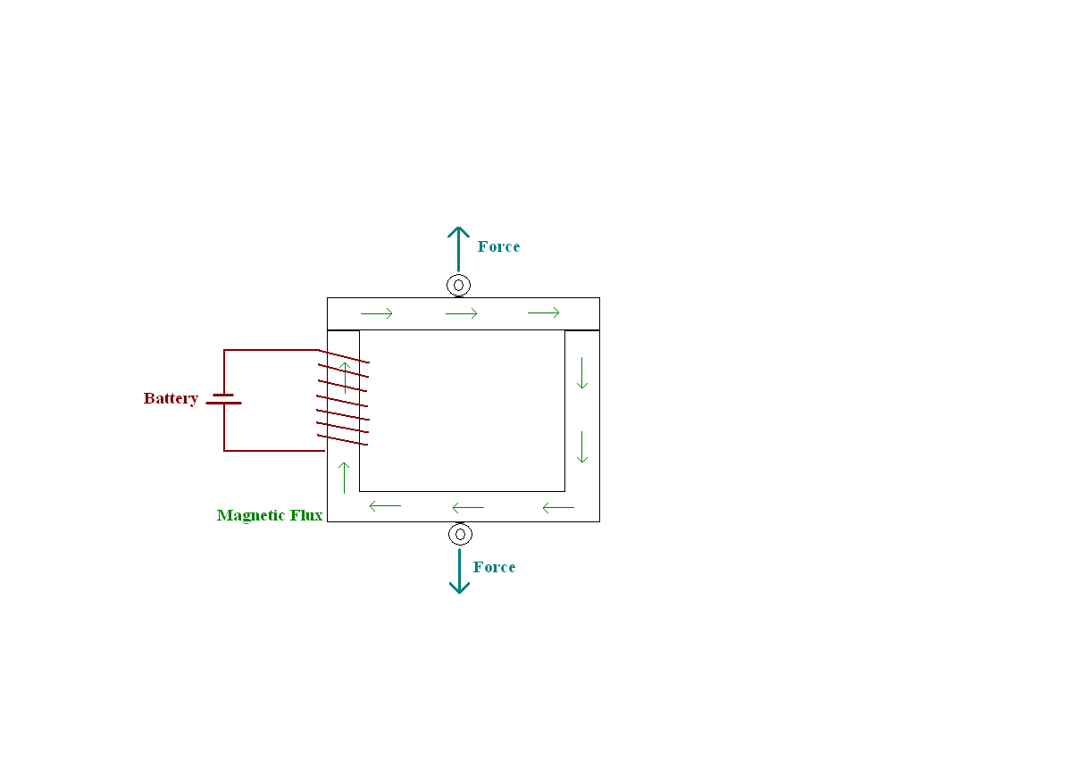
Elektromagnet
A square shaped iron core is composed by putting a U-shaped core and an I-shaped core in position. A coil is placed around one leg of the core and it is connected to a battery. From the moment the coil gets activated, it becomes impossible to separate both ends of the core. The core is hold together by the force of a very strong magnetic field. The amount of current fed into the coil is related to the magnetic field that is generated in the core. (see magnetization or B-H curve below). When the coil is no longer activated, no force is needed for separation of both cores as the magnetic field has disappeared.
This unique behavior of an electromagnet is explained by the ferromagnetic properties of the iron core material.
Ferromagnetic materials consist of small magnetic areas at the atomic level called Weiss-areas. As long as all these areas are oriented in different directions, the bulk material remains unmagnetized. Under influence of an external magnetic field, the Weiss areas start to align themselves according to this field. This results in a magnetic field that is much stronger than the original applied field. Nevertheless when the external magnetic field is removed, some Weiss areas start again to align themselves randomly. Depending on type of ferromagnetic material, most areas will loose their alignment as the resulting external magnetic field will become smaller and smaller. So there will only remain a negligible magnetic field in the end. However, in some ferromagnetic materials a reasonable amount of Weiss areas will keep their alignment and so these materials have become real magnets because of their higher remanent magnetic field (Br). For electromagnets, the remanent magnetism is very small as it is desired to switch off the magnet completely. On the contrary for magnetic tapes, the stripe on magnetic tickets and bank cards the remanent magnetism is relatively large. This explains the capability of these materials to remember the magnetic field that was previously applied.
How much a material gets magnetized by an applied magnetic field is expressed by its permeability.
B = µH
With µ = µ0µr
Where:
B: magnetic flux density (Wb/m²)
H: applied magnetic field (A/m)
µ0: permeability of free space
µr: relative permeability
The relative permeability of a material indicates its capability to conduct a magnetic field. It describes how much larger the magnetic flux density generated by a coil will be compared to an air coil.
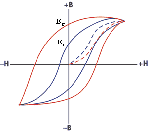
Magnetization curve
As you can see in the magnetization curve, the relation between magnetizing field H and the magnetic flux density B is not a constant. The relative permeability can vary with the position in the medium, the frequency of the field applied, humidity, temperature, and other parameters. Each material will have its own curve and hereby its own remanence (Br).
In an electromagnet the Weiss areas are lined up with each other by imposing a small external field coming from a solenoid. According to Ampere’s law, every current conductor generates a magnetic field. For a solenoid, the magnetic fields around each wire sums up and magnetic flux lines flow similar to the picture shown below. All flux lines are closed loops, but the biggest loops on the picture are interrupted for convenience.
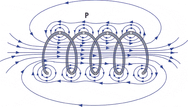
The magnetic field inside an air coil
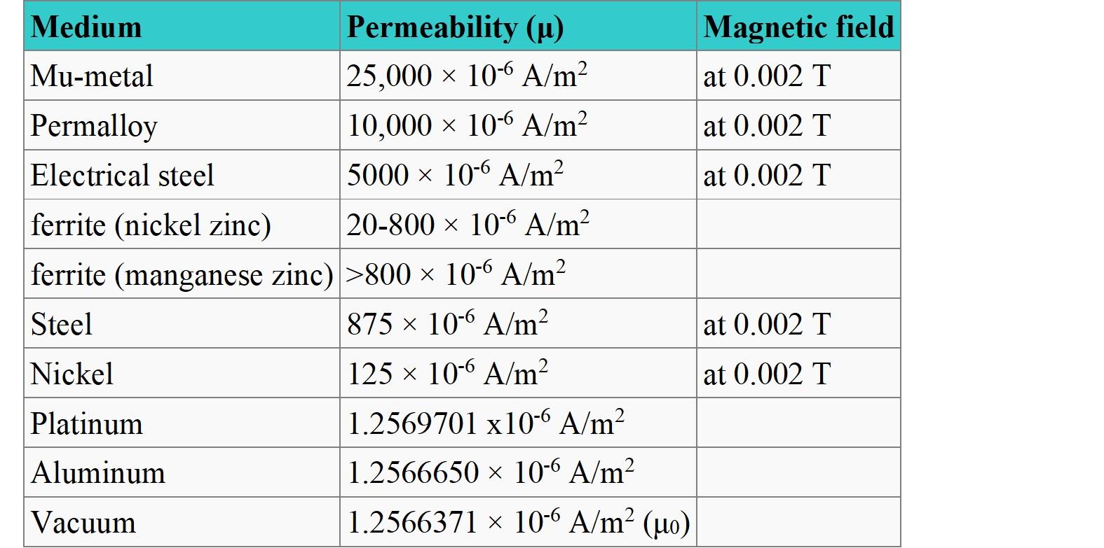
When we take the core material into account, the behavior will be slightly different. As the core material will have a much higher permeability compared to air, only a negligible part of the flux lines will close through the air. All flux lines will now flow through the core which is the easiest way to close. The following table shows the permeability of some materials. As can be seen, there can be a big difference in permeability amongst materials which explains the difference in magnetic behavior.
In spite of size, the difference between a magnetic head and an electromagnet is caused by the gap in the core material. This small barrier forces the flux lines to emerge from the core. The flux lines now continue their path along the magnetic medium as this material conducts the flux lines more easy than the gap material, or else the magnetic medium has a larger permeability. As already mentioned above, the magnetic medium has a relatively large remanent magnetic field and thus it has the property to “remember” the flux generated in the core. Hence, a magnetic signal is stored on the medium according to the electrical signal through the solenoid. The picture below shows graphically what happens during a recording cycle. The Weiss areas are randomly aligned on the medium before recording. Under influence of the emerging field of the core, the Weiss areas align themselves according to this field. This alignment is maintained when the field is removed. The result is a magnetic storage corresponding with the applied magnetic field that was generated by the current in the coil.
Reading process
Getting back data from a magnetic medium by means of a magnetic head is one of the many applications of Faraday’s law of induction. Faraday’s law of induction says:
Any change in the magnetic environment of a coil of wire will cause a voltage to be induced in the coil that is proportional to the rate of this change.
It doesn’t matter how the flux change is produced, a voltage will build up in the coil. A typical experiment that is used to illustrate the law of Faraday, is to move a magnet back and forth into a coil. After connecting an analog Volt meter to the coil, you can see the needle oscillating corresponding to the movement of the magnet.
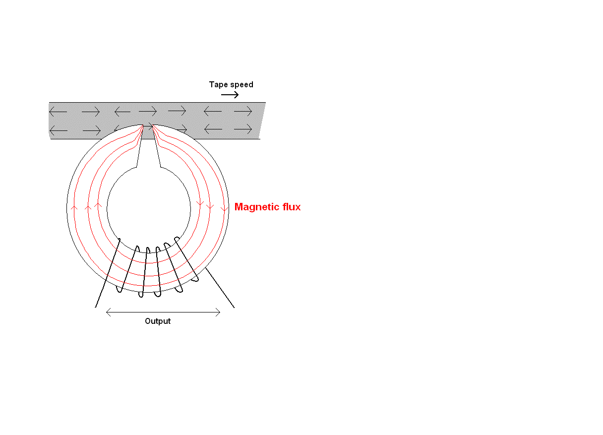
In a magnetic head the situation is very similar. The change in magnetic flux is picked up at the gap of the magnetic head and transferred through the core to the coil windings. The output level of the magnetic head is generated by the flux changes on the magnetic medium that are picked up at the magnetic head’s gap. This is illustrated in the picture below.
As it can be derived from the formula, the output will vary corresponding to the magnitude of flux change over time (speed) and also when the amount of coil windings is increased.
There can be a big difference amongst the quality of magnetic heads coming from different suppliers. Generally the differences show up when taking a closer look at the alignment of the core material, the gap, the head’s mounting position in its support,…
Also the final polish of a magnetic head is very important to guarantee a proper contact with the magnetic medium. The surface finish can vary very much from one supplier to another.
The way of production and material usage will determine how good all manufacturing processes are controlled. This will result in great repeatability and consistency that can be seen when interpreting the test results.
A good alignment and surface finish combined with a well controlled manufacturing process will be the key in guaranteeing a reliable product with good efficiency.
Magnetic heads wear because they are in contact with the media that is used for reading from or writing to. One possibility to slow down the wearing process is to shift to harder core materials which make the magnetic head more durable. Another possibility to enlarge the lifetime of a magnetic head is to provide a ceramic coating on its surface.
Both solutions will slow down the wear process substantially.
When it comes down to the lifetime of a magnetic head, it is very important that all other features are set properly. For instance the positioning of a pressure roller, the tension adjusted on a pressure roller and the position of the magnetic head are all parameters that play an important role in preventing premature wear.
Most often problems in magnetic encoding are caused by a poor contact between the gap of the magnetic head and the magnetic medium.
Two common problems with the positioning of the magnetic head can occur and are easily verified. The first issue is called azimuth and this comes from an incorrect angle between the gap of the magnetic head and the magnetic track. This angle should be perpendicular and if not, this will result in reading errors. The second issue is called tilt and occurs when the magnetic medium does not run parallel to the surface of the magnetic head. Both problems can be better understood when looking at the picture bellow.
Azimuth and tilt can be easily detected when you visualize the signal on an oscilloscope. If there is a noticeable difference between signal magnitude of the outer tracks, there is a problem with tilt. There is a poor contact between the magnetic head and the magnetic medium on the track with lower output. This will also show up in the wear pattern of the magnetic head.
Azimuth can be identified as when the signal itself is transformed. Pulses become wider and peaks will significantly drop as the signal on the magnetic medium is more or less spread out.
Another way of detecting azimuth and tilt is by visualizing the signal on the magnetic track itself. Visualization is performed by spraying a mixture of alcohol and iron particles on the magnetic medium. The iron particles align themselves according to the magnetic fields on the tape and make it possible for the human eye to see the bit stream for every recorded track on the medium. If the stripes of the visualized signal are oblique, this means there is azimuth. Tilt can be detected if you see one track is missing or there is a noticeable difference in intensity of iron particles between tracks.
Other things that often cause an unexpected decrease in performance of a card reader can come from a firmware update or the change of supplier for rollers, tickets, etc.
Contact us with your requirements or mail a picture of the head and we will match it to one of our own.
Contact usWhen you visit a website, this information can be stored or retrieved in your browser, usually in the form of cookies. This information may be about you, your preferences or your device and is usually used to make the site work as you expect. The information doesn't usually identify you directly, but it can give you a more personalized web experience. Because we respect your right to privacy, you can choose not to allow certain types of cookies. Click on the various category headings to learn more and change the default settings. However, blocking some types of cookies can affect your experience with the site and the services we can provide.
Atealaan 3
2270 Herenthout
Belgium
Phone: +32 14 400 611
Fax: +32 14 400 629
E-mail: info@ambelgium.be